Connect to PLC (Ethernet/IP, PROFINET)
This guide shows you how to connect your OV20i camera to industrial PLCs using EtherNet/IP or PROFINET protocols. These connections enable real-time communication for triggering inspections, receiving results, and integrating vision inspection into your automated production systems.
When to Use PLC Communication: When you need to integrate vision inspection with automated production lines, trigger inspections from PLC signals, send pass/fail results to PLCs, or coordinate vision inspection with other automation equipment.
Prerequisites
- OV20i camera system set up and connected to network
- PLC system with EtherNet/IP or PROFINET capability
- Network infrastructure connecting camera and PLC
- Access to PLC programming software (Studio 5000, TIA Portal, etc.)
- Basic understanding of industrial networking concepts
Understanding PLC Communication Protocols
EtherNet/IP
- Used by: Allen-Bradley/Rockwell Automation PLCs primarily
- Benefits: High-speed communication, widely supported, explicit and implicit messaging
- Applications: ControlLogix, CompactLogix, and other Rockwell platforms
- Data Exchange: Cyclic I/O and message-based communication
PROFINET
- Used by: Siemens and other European manufacturers
- Benefits: Real-time deterministic communication, advanced diagnostics
- Applications: Siemens S7 PLCs, various industrial automation systems
- Data Exchange: Cyclic I/O with real-time performance
Part 1: EtherNet/IP Connection
Step 1: Configure OV20i for EtherNet/IP
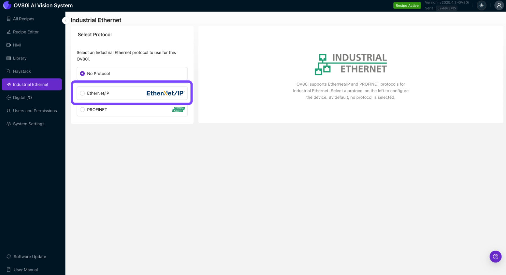
1.1 Access Industrial Ethernet Settings
- Open the OV20i web interface
- Navigate to "Industrial Ethernet" in the left menu
- You'll see the Industrial Ethernet configuration page
1.2 Enable EtherNet/IP Protocol
- In the Industrial Ethernet menu, select "EtherNet/IP" protocol
- Click "Enable" to activate EtherNet/IP communication
- Note your camera's network settings in the Device Information window
1.3 Configure Network Settings
- Set Static IP Address (recommended for production)
- Go to System Settings > Network
- Configure static IP in same subnet as your PLC
- Example: Camera: 192.168.1.100, PLC: 192.168.1.50
- Configure Subnet Mask (typically 255.255.255.0)
- Set Gateway if required for your network
1.4 Configure EtherNet/IP Device Settings
- Device Name: Set a meaningful name for your camera
- Assembly Configuration: Configure input/output data structures
- Connection Parameters: Set appropriate timeout and RPI (Requested Packet Interval) values
- Click "Save" to apply EtherNet/IP settings
Step 2: Configure PLC Recipe Settings
2.1 Enable PLC Triggering (Optional)
- Navigate to Recipe Editor > Imaging Setup
- In Photometric Control, set Trigger Mode to "PLC Trigger"
- Important: Once PLC Trigger is enabled, manual triggering is disabled
2.2 Configure Pass/Fail Output
- Navigate to Recipe Editor > IO Block
- Ensure your inspection logic ends with "Final Pass/Fail" node
- This sets the Inspection Pass bit in the EtherNet/IP assembly
Step 3: Configure PLC Side (Allen-Bradley Example)
3.1 Install EDS File
- Download EDS file from Overview.ai support or camera interface
- In Studio 5000, go to Tools > EDS Hardware Installation Tool
- Browse and select the OV20i EDS file
- Follow the installation wizard to complete EDS installation
3.2 Add OV20i Module to PLC Project
- In Studio 5000, open your PLC project
- Go to I/O Configuration in the project tree
- Right-click on Ethernet module and select "New Module"
- Search for "OV20i" or "Overview" in the module catalog
- Select the OV20i module and click "Create"
3.3 Configure Module Properties
- Name: Enter descriptive name for the camera
- IP Address: Enter the OV20i's IP address (e.g., 192.168.1.100)
- RPI (Requested Packet Interval): Set to 100ms or as required
- Connection Parameters: Configure input/output data sizes
- Click "OK" to create the module
3.4 Map I/O Data
- Input Data: Inspection results, status bits, camera ready signals
- Output Data: Trigger commands, recipe change requests, control signals
- Create tags in your PLC program to map to the I/O data
- Example Input Tags:
Camera_InspectionPass: BOOLCamera_Ready: BOOLCamera_Busy: BOOL
- Example Output Tags:
Camera_Trigger: BOOLCamera_RecipeSelect: INT
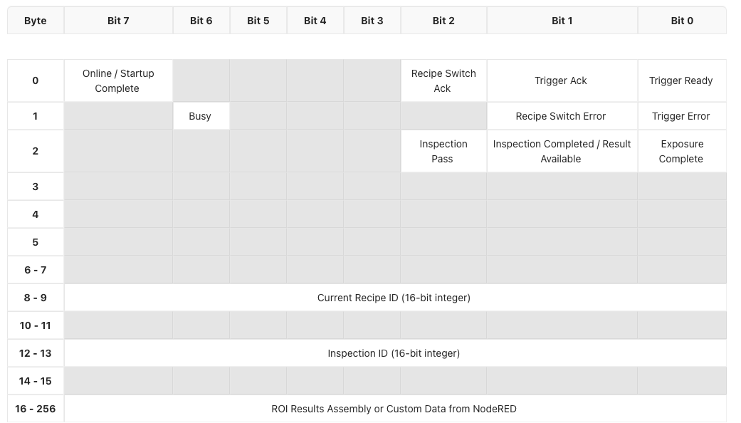
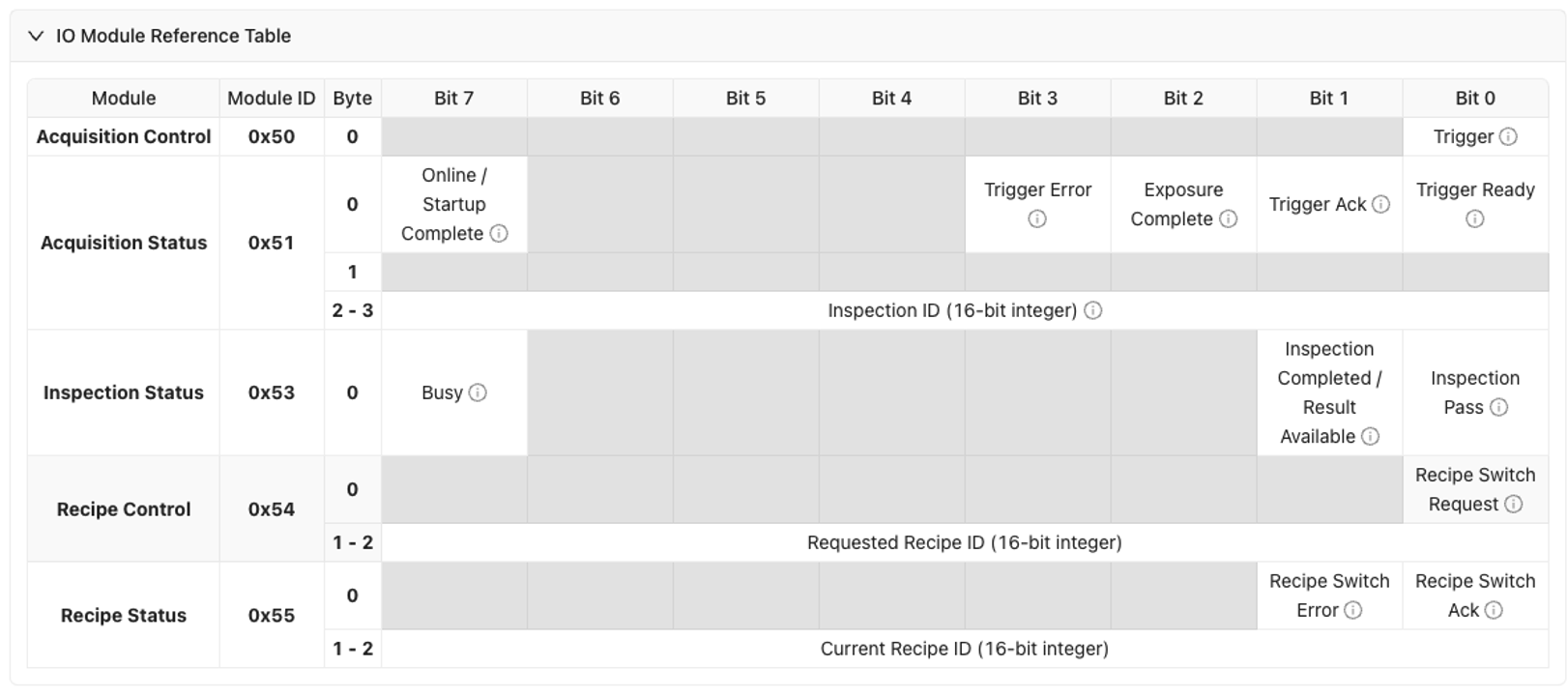
Input Assembly (OV20i → PLC)
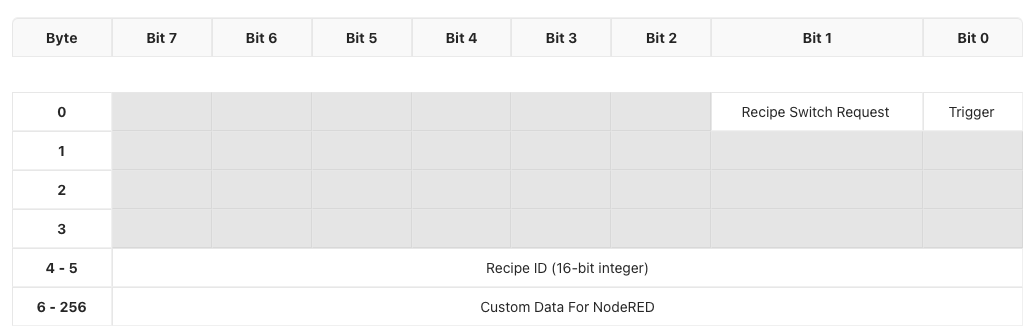
Output Assembly (PLC → OV20i)
Step 4: Test EtherNet/IP Communication
4.1 Verify Connection Status
- In Studio 5000, check module status in I/O Configuration
- Green checkmark indicates successful connection
- Red X indicates communication issues
4.2 Test Basic Communication
- Monitor input data from camera in PLC program
- Toggle output signals to camera and verify response
- Check diagnostic information for any error codes
4.3 Test Trigger and Response
- Enable PLC trigger output to camera
- Monitor inspection results in PLC input data
- Verify pass/fail status updates correctly
- Check timing of trigger and response cycles
Part 2: PROFINET Connection
Step 1: Configure OV20i for PROFINET
1.1 Access Industrial Ethernet Settings
- Open the OV20i web interface
- Navigate to "Industrial Ethernet" in the left menu
- Select "PROFINET" protocol from the options
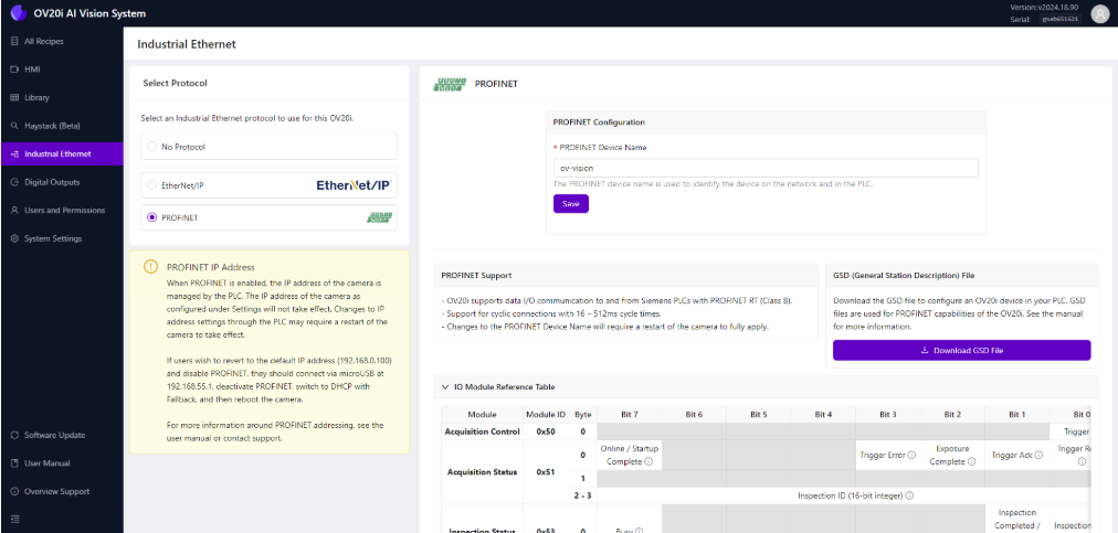
1.2 Enable PROFINET Protocol
- Click "Enable PROFINET" to activate protocol
- Note: PROFINET manages camera IP address when enabled
- Camera IP settings may be overridden by PLC configuration
1.3 Configure PROFINET Device Settings
- PROFINET Device Name: Set unique name for camera
- Example: "OV20i_Line1_Station2"
- Must be unique if multiple cameras on same PLC
- Device Configuration: Note the device capabilities and data structure
- Click "Save" to apply PROFINET settings
Step 2: Configure PLC Recipe Settings
2.1 Enable PLC Triggering (Optional)
- Navigate to Recipe Editor > Imaging Setup
- Set Trigger Mode to "PLC Trigger" if needed
- Warning: Manual triggering disabled when PLC trigger is active
2.2 Configure Pass/Fail Logic
- Navigate to Recipe Editor > IO Block
- Ensure inspection logic concludes with "Final Pass/Fail" node
- This sets the Inspection Pass bit in PROFINET input assembly
Step 3: Configure PLC Side (Siemens Example)
3.1 Install GSDML File
- Download GSDML file from Overview.ai support
- In TIA Portal, go to Options > Manage general station description files (GSD)
- Click "Install GSD file" and select the OV20i GSDML file
- Complete the installation process
3.2 Add OV20i to Hardware Configuration
- In TIA Portal, open Device & Networks view
- From the Hardware catalog, expand Other field devices > PROFINET IO
- Locate OV20i device and drag it to the network view
- Connect the OV20i to your PLC's PROFINET interface
3.3 Configure Device Properties
- Device Name: Set same name as configured in camera
- IP Address: Configure IP address (may be managed by PLC)
- Update Time: Set cycle time (default 128ms recommended)
- I/O Data: Configure input/output data modules as needed
3.4 Assign IP Address and Device Name
- Compile hardware configuration
- Go online with PLC
- Assign IP address to OV20i device
- Assign device name matching camera configuration
Step 4: Test PROFINET Communication
4.1 Verify Device Status
- In TIA Portal, check device status in Device & Networks
- Green status indicates successful communication
- Red status indicates communication problems
4.2 Test Data Exchange
- Monitor input data from camera in PLC program
- Control output data to camera and verify response
- Check diagnostic buffers for any error messages
4.3 Test Inspection Cycle
- Activate PLC trigger to camera
- Monitor inspection results in PLC input data
- Verify pass/fail status transmission
- Check cycle timing meets application requirements
Step 5: Troubleshooting PLC Communication
5.1 Common EtherNet/IP Issues
| Problem | Symptoms | Solution |
|---|---|---|
| Connection timeout | Module shows red X in Studio 5000 | Check IP addresses, network connectivity, firewall settings |
| Data not updating | I/O data remains static | Verify EDS file version, check assembly configuration |
| Trigger not working | Camera doesn't respond to PLC trigger | Check trigger bit mapping, verify PLC output is active |
| Slow response | Delayed inspection results | Adjust RPI timing, check network load |
5.2 Common PROFINET Issues
| Problem | Symptoms | Solution |
|---|---|---|
| Device not found | Camera not visible in TIA Portal | Check GSDML file installation, verify device name |
| IP address conflicts | Communication errors | Ensure unique IP addresses, check subnet configuration |
| Cycle time errors | Watchdog timeouts | Increase cycle time, check network performance |
| Data format errors | Incorrect I/O data | Verify GSDML version, check data structure mapping |
5.3 Network Diagnostics
- Ping test between camera and PLC
- Check network switches and cable integrity
- Monitor network traffic for bandwidth issues
- Verify firewall settings don't block communication
Step 6: Performance Optimization
6.1 Timing Considerations
- EtherNet/IP RPI: Start with 100ms, adjust based on application needs
- PROFINET Cycle Time: Use 128ms default, reduce only if required
- Inspection Time: Consider total inspection time in cycle planning
- Network Latency: Account for network delays in timing calculations
6.2 Data Efficiency
- Minimize data size in I/O assemblies
- Use appropriate data types (BOOL vs INT vs REAL)
- Avoid unnecessary data in cyclic communication
- Use explicit messaging for non-critical data
6.3 Network Management
- Use managed switches for better diagnostics
- Implement redundancy for critical applications
- Monitor network utilization to prevent congestion
- Plan IP address ranges for scalability
Success! Your PLC Communication is Established
Your OV20i camera can now:
✅ Communicate with PLCs using industrial protocols
✅ Receive trigger signals from automation systems
✅ Send inspection results to PLC control logic
✅ Integrate seamlessly with production line automation
✅ Support remote recipe changes and system coordination
Best Practices
Production Deployment
- Use static IP addresses for consistent communication
- Document all network settings and device configurations
- Test thoroughly before production deployment
- Plan for maintenance and troubleshooting procedures
Security Considerations
- Segment industrial networks from office networks
- Use managed switches with appropriate security features
- Monitor network access and device communications
- Keep firmware updated on all network devices
Maintenance
- Regular network health checks and diagnostics
- Monitor communication statistics for performance trends
- Update device drivers and configuration files as needed
- Maintain documentation of all network configurations
Next Steps
After establishing PLC communication:
- Develop PLC control logic for your specific application
- Create operator interfaces for monitoring and control
- Set up data logging for production tracking
- Implement alarm handling for system fault management
- Plan system backup and disaster recovery procedures
📥 Download Files
Download these essential files for PLC integration:
EtherNet/IP Configuration
- OV20i EDS File - Electronic Data Sheet for Allen-Bradley Studio 5000
- Required for configuring OV20i module in ControlLogix/CompactLogix systems
PROFINET Configuration
- OV20i GSDML File - Device description for Siemens TIA Portal
- Required for configuring OV20i device in PROFINET networks
Sample PLC Code
-
Recipe Switch Routine - Ladder logic for recipe switching
- Complete Allen-Bradley routine for changing camera recipes via PLC
-
Camera Trigger Routine - Ladder logic for triggering inspections
- Complete Allen-Bradley routine for triggering camera and handling results
File Usage Notes:
- EDS Files: Import into Studio 5000 via Tools → EDS Hardware Installation Tool
- GSDML Files: Import into TIA Portal via Options → Manage GSD Files
- L5X Files: Import ladder logic directly into your Allen-Bradley project