Imaging Setup Walkthrough
This guide walks you through configuring imaging and lighting settings on the OV20i to achieve optimal inspection quality. It includes focus, exposure, lighting, and trigger mode setup.
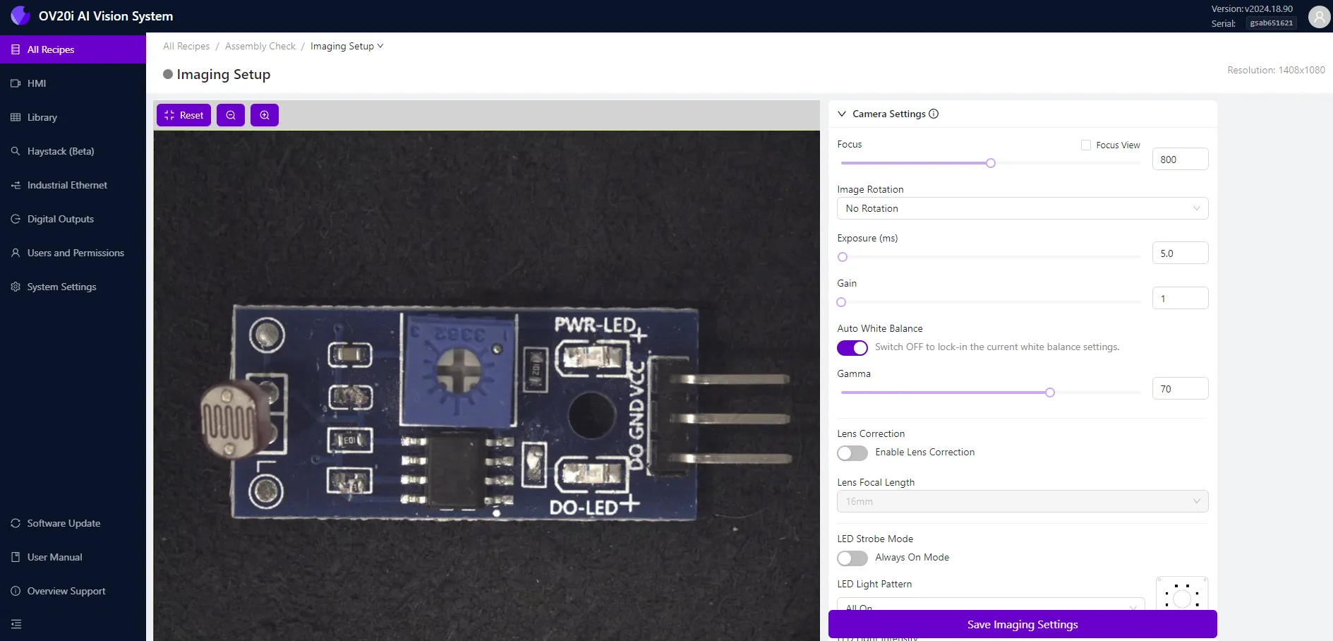
Live Preview and Zoom
- The preview pane (left side) displays a live view of the OV20i camera feed.
- Use the Zoom In / Out tools (top-left) or mouse scrollwheel to adjust preview magnification.
- Click Reset or change pages to return zoom to default.
note
Zoom only affects on-screen display, not the camera's actual field of view.
Camera Settings
| Setting | Description |
|---|---|
| Focus | Adjust using the slider or numerical input. Move left for nearer objects, right for farther. |
| Focus View | Enable to highlight edges and display a focus score (top-right). A higher score = sharper focus. |
| Image Rotation | Flip the view (180°) to match user orientation. Does not affect model data. |
| Exposure (ms) | Sets shutter time. Higher = brighter image, but more motion blur. |
| Gain | Digitally brightens the image. Use with care to avoid noise. |
| Auto White Balance | Enabled by default. Auto-adjusts colors. Turn OFF before saving imaging settings. |
| Gamma | Adjust image contrast directly from the camera sensor. |
| Lens Correction | Enable and select focal length to compensate for lens distortion. |
Lighting Settings
| Lighting Option | Description |
|---|---|
| LED Strobe Mode | When enabled, LEDs flash only during image capture. When disabled, LEDs stay continuously on (recommended during setup). |
| LED Light Pattern | Choose which LED quadrants are active: left, right, top, bottom, or combinations. |
| LED Light Intensity | Adjust integrated LED brightness using the slider or input box. |
Photometric Control
Enable to improve imaging on challenging surfaces like embossed, textured, or reflective parts.
- OV20i captures multiple images with varying lighting angles.
- A composite is generated to reduce shadows and enhance feature visibility.
| Option | Description |
|---|---|
| Sequence | Choose from: Left+Right, Top+Bottom, All Sides. |
Trigger Settings
Select your desired image capture method:
| Trigger Type | Description |
|---|---|
| Manual HMI Trigger | Use Capture button from the HMI page. Recommended during setup. |
| Hardware Trigger | Trigger via physical input (button, sensor, etc.). |
| PLC Trigger | Trigger via digital signal from PLC. Requires Ethernet/IP or PROFINET setup. |
| Interval Trigger | Automatically captures at a fixed time interval. |
| Aligner Trigger | Captures only when Alignment Block detects a match. |
Advanced Trigger Options
| Setting | Description |
|---|---|
| Trigger Delay (μs) | Delay between trigger signal and image capture. |
| Trigger Debounce (μs) | Minimum time a signal must be stable to be valid. |
| Interval (ms) | Time between automatic captures (for Interval Trigger). |
| Throttle (ms) | Minimum time between any two captures. |
In PLC and Hardware trigger modes, live preview is disabled.
Use Manual HMI Trigger during setup and testing.
Save Settings
Always click Save Imaging Settings (bottom right) after adjusting focus, lighting, or trigger configuration.
Imaging Setup Tips
- Position the OV20i so the part fills as much of the frame as possible.
- Minimize ambient light — rely on OV20i's built-in LEDs to reduce shadows.
- For moving parts: lower exposure, increase gain to avoid blur.