Train a Segmenter
This guide shows you how to set up and configure the OV20i segmentation feature to automatically detect, measure, and analyze specific features or defects in your parts. Use segmentation when you need to identify irregular shapes, measure areas, or detect specific patterns that can't be handled by simple classification.
When to Use Segmentation: Surface defects, fluid spills, irregular shapes, area measurements, pattern detection, or any features where pixel-level precision is required.
Before You Start
What You'll Need
- OV20i camera system set up and connected
- Test parts with features you want to segment (e.g., sheets with pencil marks)
- Good lighting conditions for your specific application
- 15-20 sample images for training
Step 1: Create a Segmentation Recipe
1.1 Start New Recipe
- Navigate to All Recipes page
- Click
+ New Recipe(top-right corner) - Enter Recipe Name: Use descriptive name like "Pencil_Mark_Detection" or "Surface_Defect_Segmentation"
- Select Recipe Type: Choose "Segmentation" from dropdown
- Click
OKto create
![]()
1.2 Activate Recipe
- Find your recipe in the list (shows as "Inactive")
- Click
Actions > Activate - Click
Activateto confirm

✅ Result: Recipe is now active and ready for configuration.
Step 2: Access Recipe Editor
- Click
Editnext to your active recipe - Click
Open Editorto confirm

You'll now see the Recipe Editor with segmentation-specific options.
Step 3: Configure Camera Settings
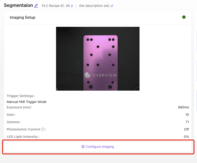
3.1 Open Imaging Configuration
- Click
Configure Imaging(lower left-hand side)
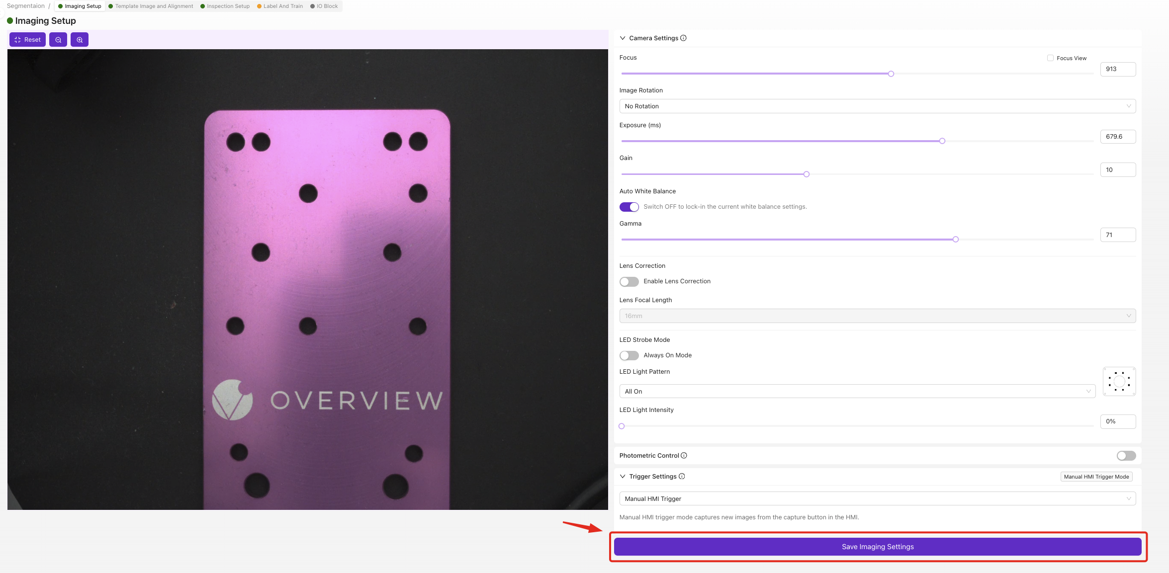
3.2 Optimize Focus for Segmentation
Focus is critical for accurate edge detection:
- Position your test part in the camera view
- Adjust Focus until edges are sharp and clear
- Test with different parts to ensure consistent focus across your range
- Focus on the surface where defects/features will appear
- Ensure the entire area of interest is in sharp focus
- Slight over-sharpening is better than soft focus for segmentation
3.3 Set Optimal Exposure
Proper exposure ensures consistent feature detection:
- Adjust Exposure for balanced lighting
- Avoid overexposed areas (pure white regions)
- Ensure features are visible with good contrast
Segmentation Exposure Guidelines:
- Features should have clear contrast with background
- Avoid shadows that could be mistaken for defects
- Test with various part conditions (clean, dirty, worn)
3.4 Configure LED Lighting Pattern
Choose lighting based on what you're segmenting:
| Feature Type | Recommended Lighting | Why |
|---|---|---|
| Surface defects | Bright field | Even illumination shows surface irregularities |
| Scratches/cracks | Side lighting | Creates shadows that highlight linear defects |
| Raised features | Dark field | Makes raised areas stand out from background |
| Liquid spills | Side lighting | Shows surface texture differences |
3.5 Adjust Gamma for Feature Enhancement
- Increase Gamma to enhance contrast between features and background
- Test different values while viewing your target features
- Find setting that makes features most distinguishable
3.6 Save Configuration
- Review settings in live preview
- Click
Save Imaging Settings
✅ Checkpoint: Features should be clearly visible with good contrast.
Step 4: Set Up Template and Alignment
4.1 Navigate to Template Section
Click "Template Image and Alignment" in breadcrumb menu
4.2 Configure Alignment (Optional)
![]()
For this example, we'll skip alignment:
- Select
Skip Alignerif parts are consistently positioned - Click
Save
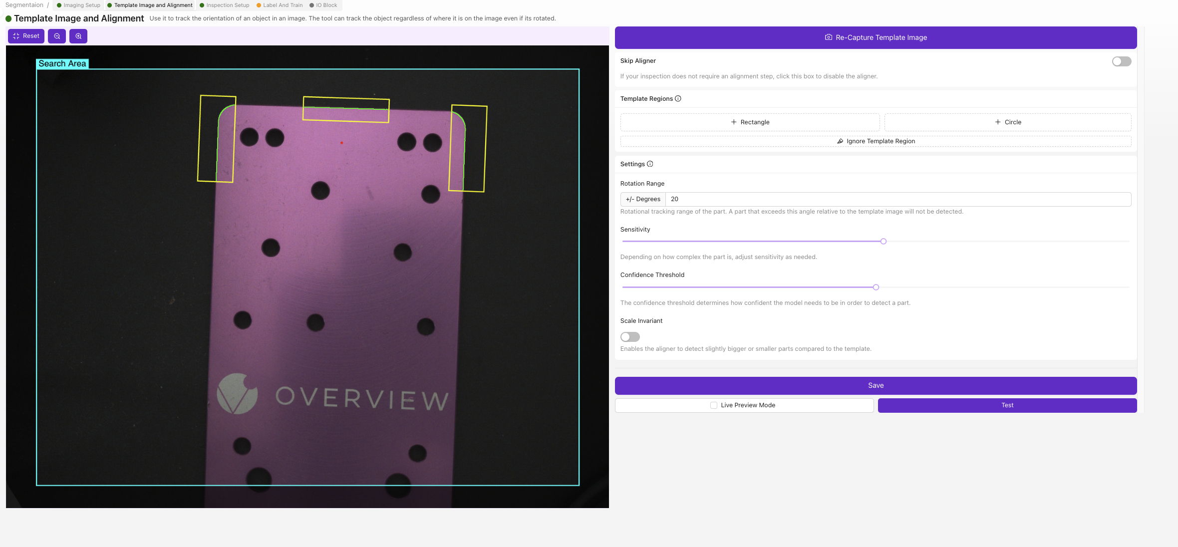
When to Use Aligner: Enable when parts arrive in varying positions or orientations that would affect segmentation accuracy.
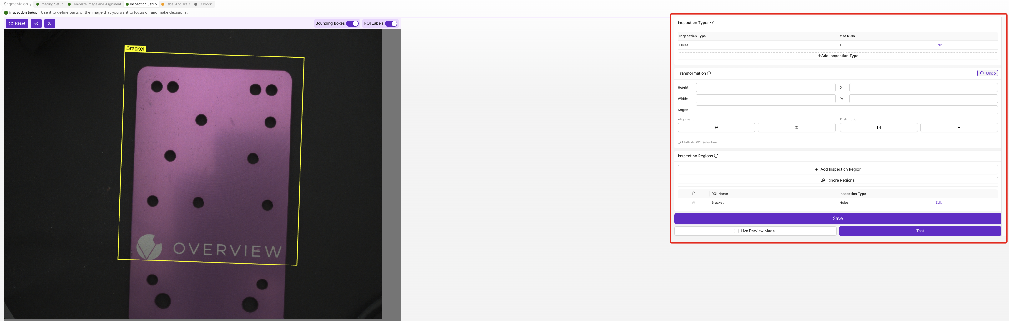
Step 5: Define Inspection Region
5.1 Navigate to Inspection Setup
Click "Inspection Setup" in breadcrumb menu
5.2 Set Region of Interest (ROI)
The ROI defines where segmentation will occur:
- Position a test part in camera view
- Drag ROI corners to frame the inspection area
- Size ROI appropriately:
- Include all areas where features might appear
- Exclude unnecessary background regions
- Leave small buffer around expected feature locations
5.3 ROI Best Practices for Segmentation
| Do | Don't |
|---|---|
| Cover entire inspection surface | Include irrelevant background objects |
| Leave buffer space around edges | Make ROI too small for feature variation |
| Consider part positioning variation | Overlap with fixtures or tooling |
| Test with largest expected features | Include areas with permanent markings |
5.4 Save ROI Settings
- Verify ROI covers all target areas
- Click
Save
Step 6: Label Training Data
6.1 Navigate to Label And Train
Click "Label And Train" in breadcrumb menu
6.2 Configure Inspection Class
- Click
Editunder Inspection Types - Rename class to match your feature (e.g., "Pencil Mark", "Surface Defect", "Spill Area")
- Choose class color for visual identification
- Save changes
6.3 Capture and Label Training Images
You need minimum 10 labeled images, but 15-20 is recommended:
Image Capture Process
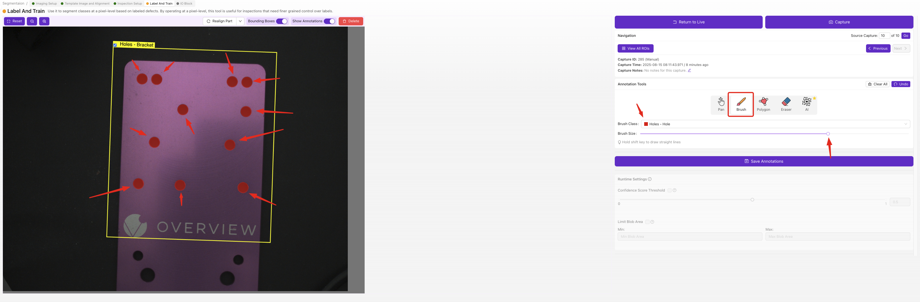
- Place first test part in inspection area
- Take image using camera interface
- Use Brush tool to paint over target features
- Paint accurately:
- Cover entire feature area
- Stay within feature boundaries
- Don't paint background areas
- Use consistent labeling approach
- Click
Save Annotations - Repeat with next part
Labeling Best Practices
| Good Labeling | Poor Labeling |
|---|---|
| Precise feature boundaries | Sloppy edge painting |
| Consistent feature definition | Inconsistent criteria |
| Complete feature coverage | Missing feature areas |
| Clean background (unpainted) | Accidental background painting |
6.4 Training Data Variety
Ensure your training set includes:
- Different feature sizes
- Various feature intensities
- Multiple locations within ROI
- Different lighting conditions (if applicable)
- Edge cases and borderline examples
6.5 Quality Check Training Data
- Review all labeled images
- Verify consistent labeling approach
- Remove any incorrectly labeled examples
- Add more examples if needed
Step 7: Train Segmentation Model
7.1 Start Training Process
- Click
Return to Livewhen labeling is complete - Click
Train Segmentation Model
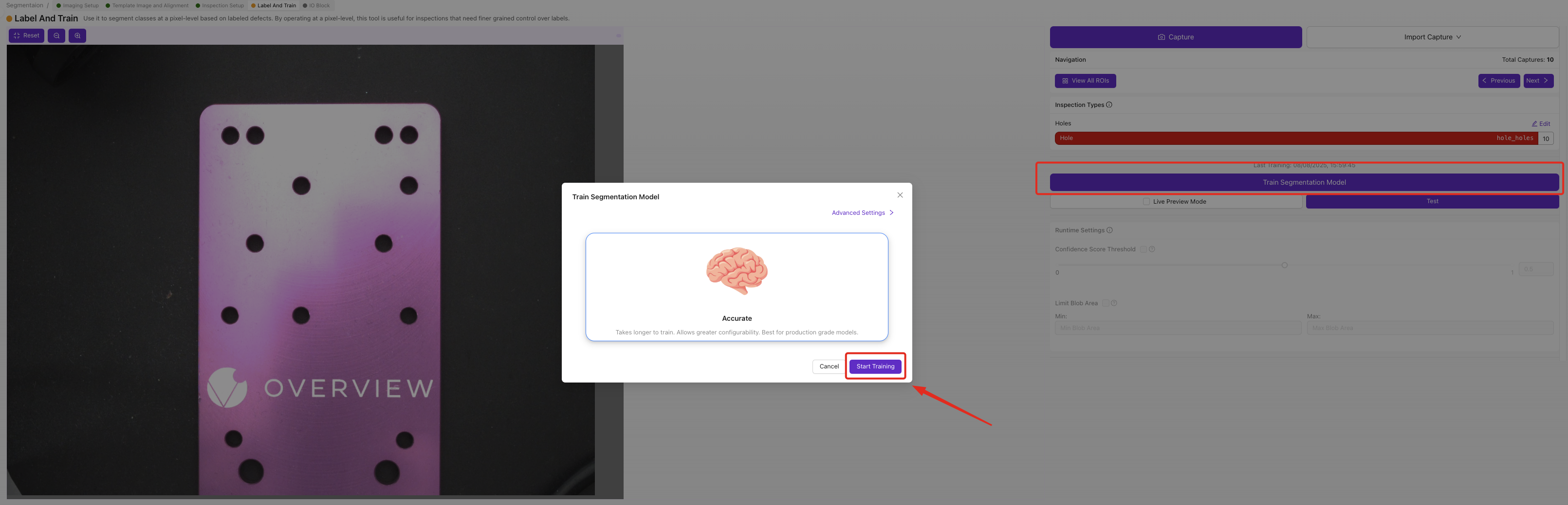
7.2 Configure Training Parameters
- Set Number of Iterations:
- Fast training: 50-100 iterations (5-10 minutes)
- Production quality: 200-500 iterations (15-30 minutes)
- High precision: 500+ iterations (30+ minutes)
- Click
Start Training
7.3 Monitor Training Progress
Training progress shows:
- Current iteration number
- Training accuracy percentage
- Estimated completion time
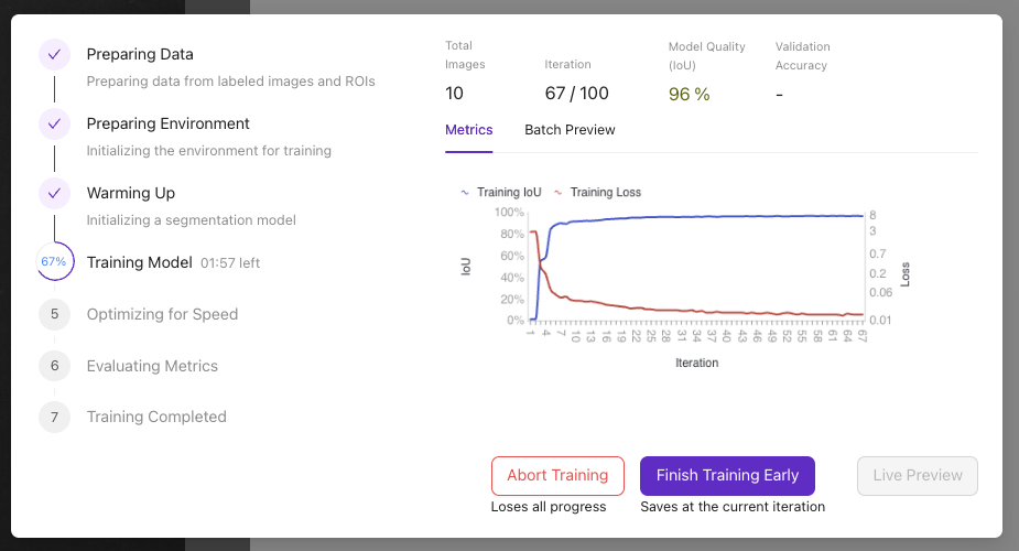
Training Controls:
- Abort Training: Stop if issues arise
- Finish Training Early: Stop when accuracy is sufficient
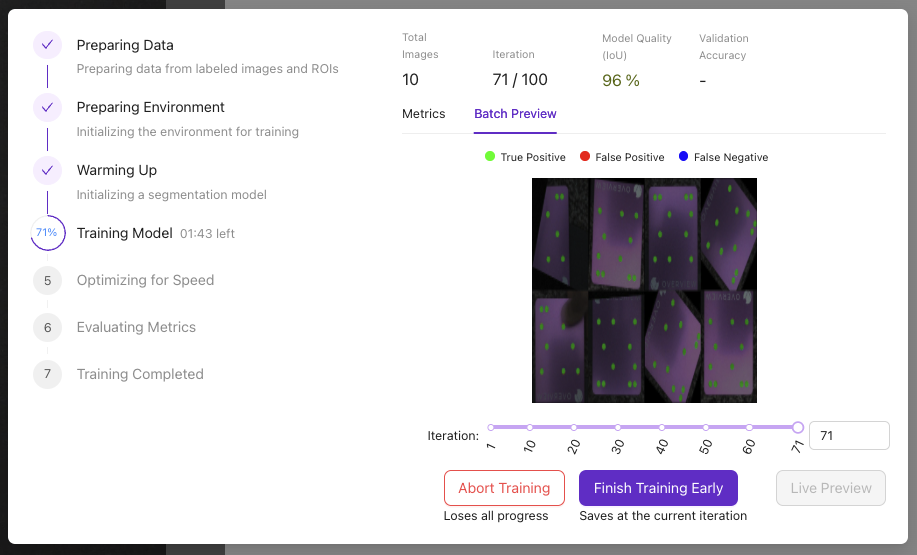
- 85% accuracy typically good for production
- Training automatically stops at target accuracy
- More training data often better than more iterations
Step 8: Test Segmentation Performance
8.1 Access Live Preview
- Click
Live Previewafter training completes - Test with various parts:
- Known good parts (should show no/minimal segmentation)
- Known defective parts (should highlight defects)
- Edge cases and borderline examples
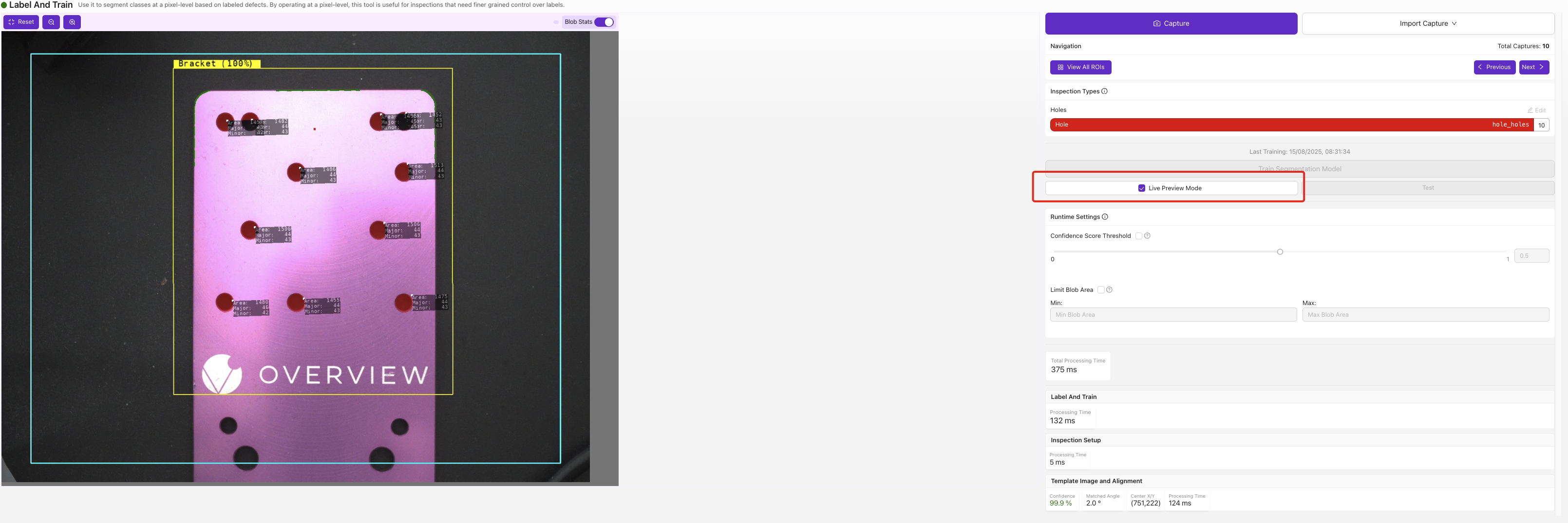
8.2 Evaluate Results
Check segmentation quality:
| Metric | Good Performance | Needs Improvement |
|---|---|---|
| Accuracy | Finds real features consistently | Misses obvious features |
| Precision | Few false positives | Many background areas highlighted |
| Edge Quality | Clean, accurate boundaries | Rough or inaccurate edges |
| Consistency | Similar results on repeat tests | Highly variable results |
8.3 Troubleshooting Poor Results
| Problem | Likely Cause | Solution |
|---|---|---|
| Missing features | Insufficient training data | Add more labeled examples |
| False positives | Poor lighting/contrast | Improve imaging settings |
| Rough edges | Poor image quality | Improve focus/lighting |
| Inconsistent results | Inadequate training variety | Add more diverse examples |
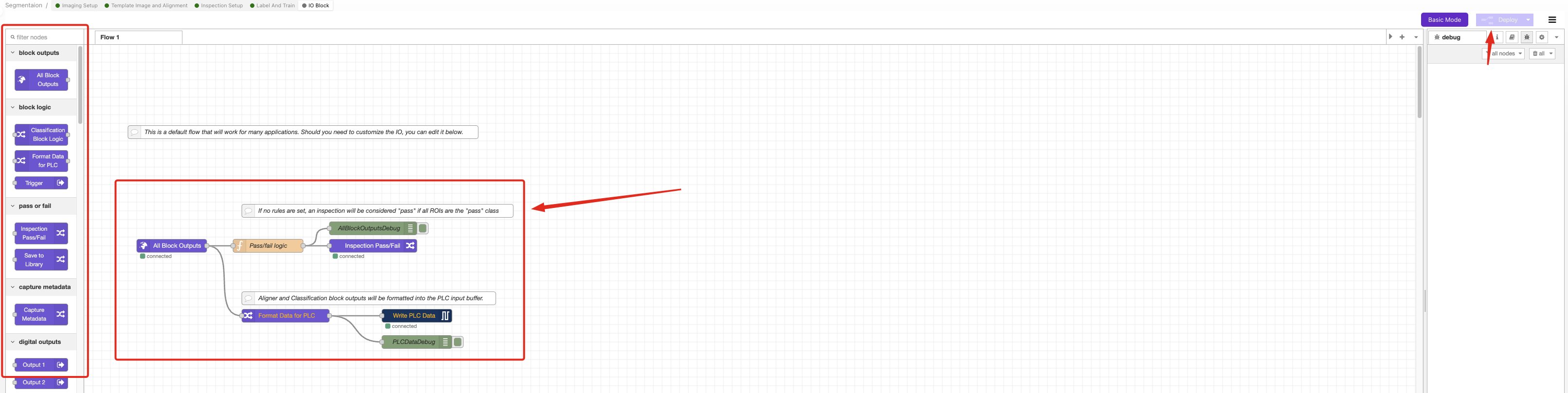
Step 9: Configure Pass/Fail Logic
9.1 Access IO Block
- Ensure AI model shows green (trained status)
- Navigate to IO Block via breadcrumb menu
9.2 Remove Default Logic
- Delete Classification Block Logic node
- Prepare to build custom segmentation logic
9.3 Build Segmentation Flow
Create Node-RED flow with these components:
- Drag nodes from left panel:
- Function node (for logic)
- Debug node (for testing)
- Final Pass/Fail node
- Connect nodes with wires
9.4 Configure Logic Based on Your Needs
Option A: Pass if No Defects Detected
Use Case: Quality inspection where any detected feature is a fail
Function Node Code:
const allBlobs = msg.payload.segmentation.blobs;
const results = allBlobs.length < 1; // Pass if no features found
msg.payload = results;
return msg;
Option B: Pass if Small Defects Only
Use Case: Accept minor defects below size threshold
Function Node Code:
const threshold = 500; // Adjust pixel count threshold
const allBlobs = msg.payload.segmentation.blobs;
const allUnderThreshold = allBlobs.every(blob => blob.pixel_count < threshold);
msg.payload = allUnderThreshold;
return msg;
Option C: Pass if Total Defect Area is Small
Use Case: Accept parts with limited total defect area
Function Node Code:
const threshold = 5000; // Adjust total pixel threshold
const allBlobs = msg.payload.segmentation.blobs;
const totalArea = allBlobs.reduce((sum, blob) => sum + blob.pixel_count, 0);
msg.payload = totalArea < threshold;
return msg;
9.5 Configure Function Node
- Double-click Function node
- Copy appropriate code from examples above
- Paste into "On Message" tab
- Adjust threshold values for your application
- Click
Done
9.6 Deploy and Test Logic
- Click
Deployto activate logic - Navigate to HMI for testing
- Test with known good and bad parts
- Verify pass/fail results match expectations
Step 10: Production Validation
10.1 Comprehensive Testing
Test segmentation system with:
| Test Case | Expected Result | Action if Failed |
|---|---|---|
| Clean parts | Pass (no segmentation) | Adjust thresholds or retrain |
| Minor defects | Pass/Fail per your criteria | Refine logic parameters |
| Major defects | Fail (clear segmentation) | Check model accuracy |
| Edge cases | Consistent behavior | Add training data |
10.2 Performance Validation
Monitor these metrics:
- Processing time per inspection
- Consistency across multiple tests
- Accuracy with production lighting
- Reliability over extended operation
10.3 Final Adjustments
If performance isn't satisfactory:
- Add more training data for edge cases
- Adjust threshold values in logic
- Improve imaging conditions
- Retrain model with additional iterations
Success! Your Segmentation System is Ready
You now have a working segmentation system that can:
- Automatically detect specific features or defects
- Measure areas with pixel-level precision
- Apply custom pass/fail logic based on your requirements
- Integrate with production systems via I/O controls
Advanced Configuration Options
Custom Threshold Logic
For complex acceptance criteria, combine multiple conditions:
const smallThreshold = 200;
const largeThreshold = 1000;
const maxTotalArea = 3000;

const allBlobs = msg.payload.segmentation.blobs;
const smallBlobs = allBlobs.filter(blob => blob.pixel_count < smallThreshold);
const largeBlobs = allBlobs.filter(blob => blob.pixel_count > largeThreshold);
const totalArea = allBlobs.reduce((sum, blob) => sum + blob.pixel_c