Use the Aligner Tool
This guide shows you how to use the OV20i Aligner Tool to automatically detect and align parts for consistent inspection. The Aligner Tool uses template matching to locate parts that may be positioned differently in each image, ensuring your Regions of Interest (ROIs) always inspect the correct areas.
When to Use the Aligner Tool: When parts are not consistently positioned, when using conveyor systems, when parts can rotate or shift, or when you need automatic part detection and alignment before inspection.
Prerequisites
- OV20i camera system set up with proper imaging configuration
- Template Image captured with a well-positioned part
- Understanding of your part's key features for alignment
- Access to Template Image and Alignment page in Recipe Editor
What is the Aligner Tool?
The Aligner Tool automatically locates and orients parts using pattern matching:
- Detects parts that may be positioned differently in each capture
- Aligns ROIs to match the detected part position and rotation
- Uses edge detection to find consistent patterns in your parts
- Compensates for position, rotation, and scale variations
Key Benefits:
- Consistent inspection even when parts move or rotate
- Automatic part detection without manual positioning
- Reliable inspection on conveyor systems or loose fixtures
- Compensation for small variations in part placement
Step 1: Access the Aligner Tool
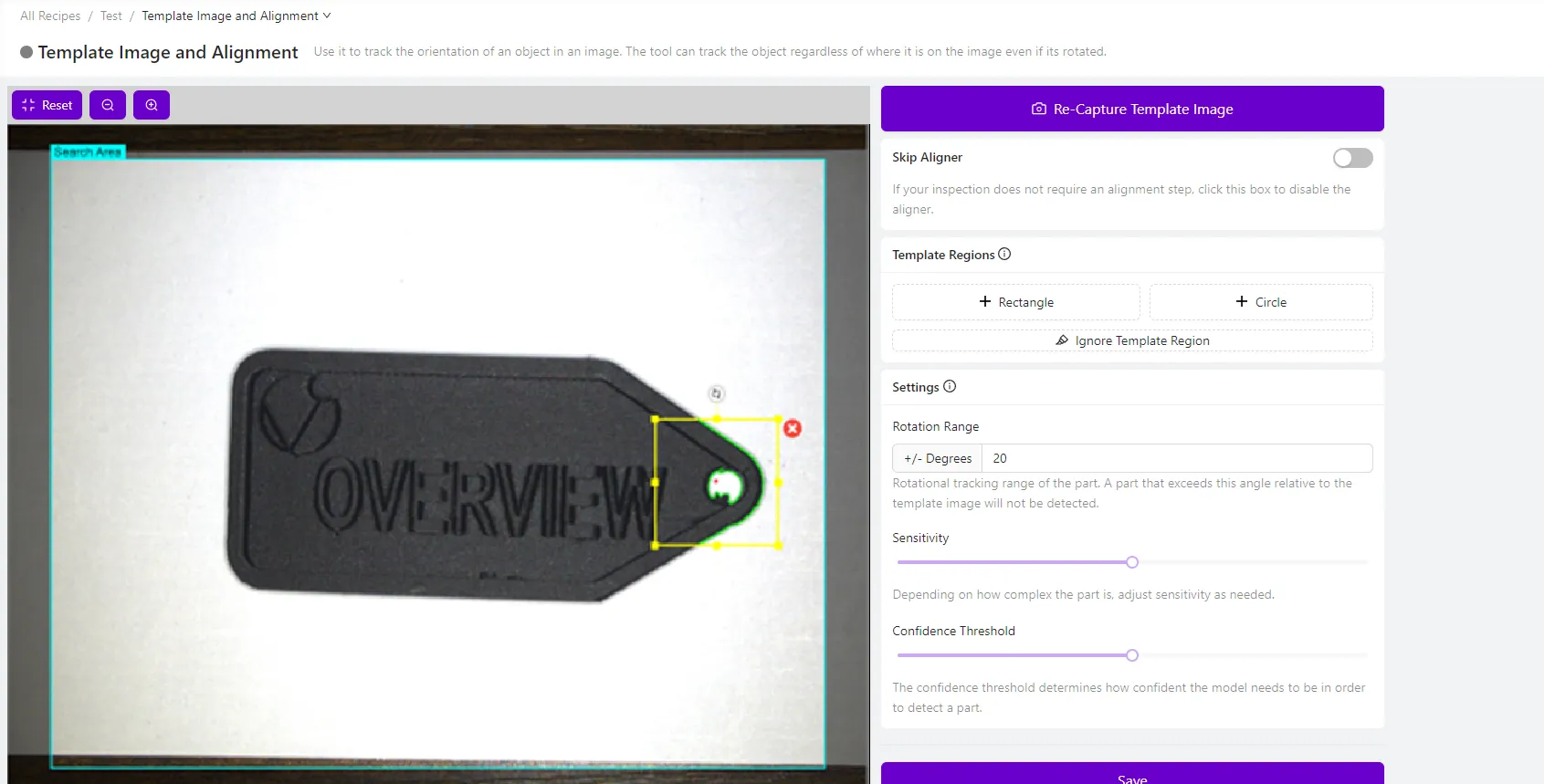
1.1 Navigate to Template Image and Alignment
- Open your recipe in Recipe Editor
- Click "Template Image and Alignment" in the left menu
- Ensure you have captured a Template Image (if not, see Step 2)
1.2 Verify Template Image Quality
Your Template Image should show:
- A well-positioned, typical example of your part
- Good lighting with clear edge definition
- All areas you want to inspect visible
- Minimal shadows, reflections, or debris
Checkpoint: You should see your Template Image displayed in the preview pane with clear, well-defined edges.
Step 2: Capture or Update Template Image
2.1 Position Your Part for Template Capture
- Place a good example part in the camera's field of view
- Ensure the part is:
- Well-lit with clear edge definition
- Properly oriented in the desired position
- Clean without debris or contamination
- Representative of typical parts you'll inspect
2.2 Capture Template Image
- Click "Capture Template Image" (or "Re-Capture Template Image" if updating)
- Wait for the image to be captured and processed
- Verify the image quality meets your requirements
Template Image Best Practices:
- Use good lighting to highlight important edges
- Avoid overexposed or underexposed areas
- Ensure the part fills an appropriate portion of the field of view
- Choose a part that represents the typical condition you'll inspect
Step 3: Enable the Aligner
3.1 Turn On Alignment
- Ensure the Aligner is enabled (not disabled)
- If disabled, the system will show "Select to disable the aligner and use fixed-position Regions of Interest"
- Keep the aligner enabled for parts that may move or rotate
3.2 Understand When to Disable Aligner
Disable the aligner only when:
- Parts are fixtured in exactly the same position every time
- Using jigs or fixtures that guarantee consistent part placement
- Parts never move, rotate, or shift between captures
- You need maximum processing speed and parts are always positioned identically
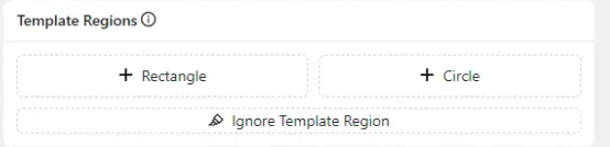
Step 4: Add Template Regions
4.1 Add Your First Template Region
- Click "+ Rectangle" or "+ Circle" to add a Template Region
- Position the region over a distinctive edge pattern on your part
- Size the region to capture important edges without including noise
4.2 Choose Good Edge Patterns
Look for patterns that are:
- Simple - Clear, well-defined edges
- Unique - Distinctive to your part, not found in background
- Consistent - Visible on every part you'll inspect
- Stable - Won't change due to lighting or part variations
Avoid patterns with:
- Textured surfaces that create complex edge noise
- Reflective areas that vary with lighting
- Areas that may be damaged or missing on defective parts
- Very fine details that may not be reliably detected
4.3 Position and Size Template Regions
- Click and drag the region to position it over good edges
- Stretch corner handles to resize the region appropriately
- Click the region to access rotation, resize, or delete options
- Aim for green highlighted edges indicating good edge detection
4.4 Add Multiple Template Regions
- Add 2-4 Template Regions for robust alignment
- Distribute regions across different areas of your part
- Each region should capture different distinctive features
- More regions provide better alignment accuracy and reliability
Step 5: Optimize Edge Detection
5.1 Check Edge Detection Quality
Good edge detection shows:
- Green highlighted edges in Template Regions
- Clear, well-defined patterns
- Consistent edge detection across the pattern
Poor edge detection shows:
- Red highlights indicating insufficient edges
- Noisy, scattered edge patterns
- Inconsistent or weak edge detection
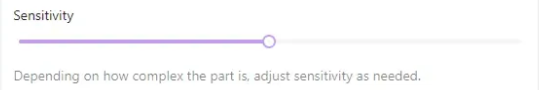
5.2 Adjust Sensitivity
If edge detection is insufficient:
- Increase sensitivity to detect more subtle edges
- Add more Template Regions to capture additional patterns
- Improve lighting to enhance edge contrast
5.3 Remove Edge Noise with Ignore Tool
- Click "Ignore Template Region" to access the brush tool
- Paint over unwanted edge highlights in red
- Focus on removing:
- Textured surface noise
- Reflective spots or glare
- Debris or contamination edges
- Background patterns
Before and After Ignore Tool:
- Before: Edge finder highlights shiny areas, textures, and noise
- After: Only clean, consistent edge patterns remain highlighted
![]()
Step 6: Test Alignment Performance
6.1 Test with Different Parts
- Place different example parts in various positions
- Use Live Preview Mode to see real-time alignment
- Observe how well the aligner detects and locates each part
- Check that Template Regions consistently match intended features
6.2 Verify Alignment Accuracy
Good alignment shows:
- Consistent part detection across different positions
- Accurate rotation and scale compensation
- ROIs that properly align with part features
- Stable alignment without false positives
6.3 Test Edge Cases
Test alignment with:
- Parts at different angles (if rotation expected)
- Parts in different positions within the field of view
- Slightly different part variations (if applicable)
- Different lighting conditions (if they may vary)
Step 7: Adjust Confidence Threshold
7.1 Understanding Confidence Threshold
The Confidence Threshold determines how certain the aligner must be before accepting a match:
- Higher values = More selective, fewer false positives
- Lower values = More permissive, may accept marginal matches
7.2 Optimize Threshold Setting
- Start with default threshold settings
- Increase threshold if experiencing false positives (matching wrong objects)
- Decrease threshold if missing valid parts that should be detected
- Test with various parts to find the optimal balance
7.3 Signs of Threshold Issues
Threshold too low:
- Aligner matches to background objects
- False positives on non-target items
- Inconsistent alignment results
Threshold too high:
- Valid parts not detected
- Alignment frequently fails
- Good parts rejected
Step 8: Troubleshooting Alignment Issues
8.1 Alignment Inconsistent or Failing
| Problem | Symptoms | Solution |
|---|---|---|
| Pattern not simple enough | Inconsistent alignment on different parts | Choose simpler, cleaner edge patterns |
| Pattern not consistently visible | Fails on certain part variations | Select features visible on all parts |
| Not enough edges | Red highlights in Template Regions | Add more regions or increase sensitivity |
| Too much edge noise | Highlights irrelevant features | Use Ignore Template Region tool |
8.2 False Positive Alignment
| Problem | Symptoms | Solution |
|---|---|---|
| Pattern not unique enough | Matches to wrong objects | Choose more distinctive features |
| Confidence threshold too low | Accepts poor matches | Increase Confidence Threshold |
| Template regions too generic | Matches background patterns | Add more specific Template Regions |
8.3 Poor Alignment Accuracy
| Problem | Symptoms | Solution |
|---|---|---|
| Insufficient Template Regions | Alignment drifts or rotates incorrectly | Add 2-4 well-distributed regions |
| Poor Template Image quality | Inconsistent edge detection | Recapture with better lighting |
| Template Regions too small | Limited alignment precision | Resize regions to capture more edge detail |
Step 9: Optimize for Production
9.1 Template Region Best Practices
- Use 2-4 Template Regions for robust alignment
- Distribute regions across different areas of the part
- Choose permanent features that won't change or degrade
- Avoid areas prone to contamination or damage
9.2 Edge Pattern Selection
Ideal edge patterns:
- Circuit board traces or component outlines
- Machined edges or holes
- Printed markings or labels
- Geometric features like corners or curves
Avoid for edge patterns:
- Textured or rough surfaces
- Reflective or shiny areas
- Areas that may accumulate debris
- Features that vary between part lots
9.3 Lighting Optimization
- Consistent lighting improves edge detection reliability
- Avoid harsh shadows that create false edges
- Minimize reflections that interfere with edge detection
- Use the OV20i's integrated LED for consistent illumination
Success! Your Aligner Tool is Configured
Your OV20i Aligner Tool is now ready to:
✅ Automatically detect parts in varying positions and orientations
✅ Align ROIs precisely to part features regardless of movement
✅ Handle rotation and scale variations for flexible part presentation
✅ Provide consistent inspection even with loose fixturing
✅ Reject false positives while detecting all valid parts
Ongoing Maintenance
Regular Checks
- Monitor alignment performance in production
- Verify Template Regions remain clean and visible
- Check for changes in part features or lighting
- Update Template Image if part design changes
Performance Optimization
- Review alignment logs for failure patterns
- Adjust confidence thresholds based on production data
- Clean Template Regions if contamination builds up
- Update edge patterns if part features evolve
Next Steps
After setting up the Aligner Tool:
- Configure ROIs to inspect aligned part features
- Test with production parts to verify alignment reliability
- Set up inspection logic that works with aligned coordinates
- Train operators on alignment status monitoring
- Create maintenance schedule for Template Image updates