Electrical Specifications
This page outlines the electrical specs and safe operating parameters for the OV80i camera, including power requirements, I/O behavior, pin assignments, and current limits.
Power Requirements
- Input Voltage: 19–24 VDC regulated power supply
- Typical Power: 15W
- Maximum Power: 18W
- Recommended Power Supply: 24 VDC, 2 A (minimum)
Power Connector:
- M12 A-coded, 12-pin male connector
- Only pins 7 (VIN) and 8 (GND) are used for power
Digital I/O Specs
The OV80i supports 1 trigger input, 2 digital inputs, and 1 digital output through the power I/O connector:
| Type | Lines | Logic | Current Rating |
|---|---|---|---|
| Inputs | 2 | NPN-compatible (sinking logic) | – |
| Outputs | 2 | NPN open collector | 100 mA max per line |
| Trigger Input | 1 | Pull to GND to activate | – |
- Output Protection: Overcurrent protection with internal thermal fuse
- DIO GND: Must be tied to PLC/system ground for reliable input detection
I/O Connector Pinout (M12 A-Coded, 12-pin)
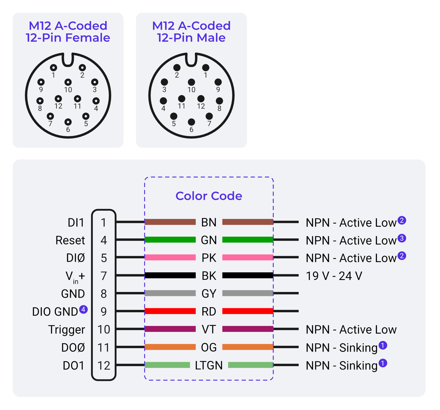
| Pin | Signal | Function |
|---|---|---|
| 1 | DI1 | NPN Active Low |
| 4 | Reset System BTN | |
| 5 | Digital Output 0 | NPN Active Low |
| 6 | Common In | |
| 7 | Power VIN | +24 VDC supply input |
| 8 | Power GND | 0V return |
| 9 | DIO GND | |
| 10 | Trigger Input | NPN trigger or dry contact |
| 11 | DO0 | Output, NPN Sinking |
| 12 | DO1 | Output, NPN Sinking |
| Others | Reserved / Not Used | No connection |
Communication Ports
| Port | Type | Use |
|---|---|---|
| RJ45 | M12 X-Coded Ethernet | Gigabit network comms |
| USB-A | USB 3.0 | For support use |
| USB-C | USB 3.0 | For support use |
- Main Camera IP (default): 10.250.0.100
Electrical Design Notes
- Use NPN-compatible sensors/relays when possible.
- Pull to GND to activate inputs.
- Outputs require external 24 V to drive loads.
- Do not exceed 100 mA per output line.
- Always connect DIO GND to external system GND for reliable operation.
Protection & Safety
- Built-in thermal fuse protects DIO GND return
- Ensure proper grounding to prevent floating inputs or noise
- Outputs are floating unless active (NPN open collector)
See Also
- Cable Specs & Part Numbers
- Digital I/O Logic: NPN vs PNP
- Troubleshooting No Trigger or Output
- Power Connector Pinout